Design and manufacture of bespoke impact test rigs
With our background in impact design and the experience that we have gained from the design and development of our own impact test facilities, we are well positioned to design, develop and manufacture bespoke facilities to meet your loadcase specification and requirements. This can include the transfer of all design rights and detailed instruction manuals.
Below are some of the test rigs that we have produced to date;
Guided Gravity Drop Test Rig – SDR 2200
Design and manufacture of a test rig for high precision drop testing
In 2015 Simpact were asked if they could carry out drop testing of several mobile phones in accordance with the transit drop procedure described in the US Department of Defence standard MIL-STD-810G. This particularly demanding test involved drop testing of the device from a height of 1.8m at specific impact orientations onto a hard surface. The issue with freefall gravity drop testing is that even with a very clean release, the drop test item invariably rotates and contacts the drop surface at different orientations. A design concept was required that delivered repeatable drop testing with consistent impact orientation and velocity.
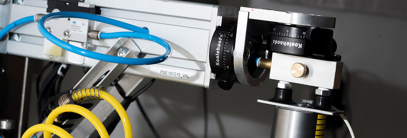
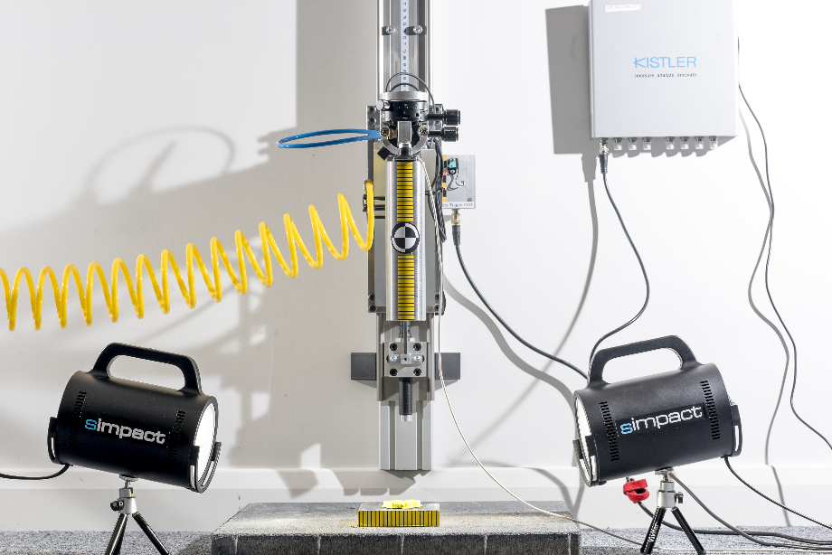
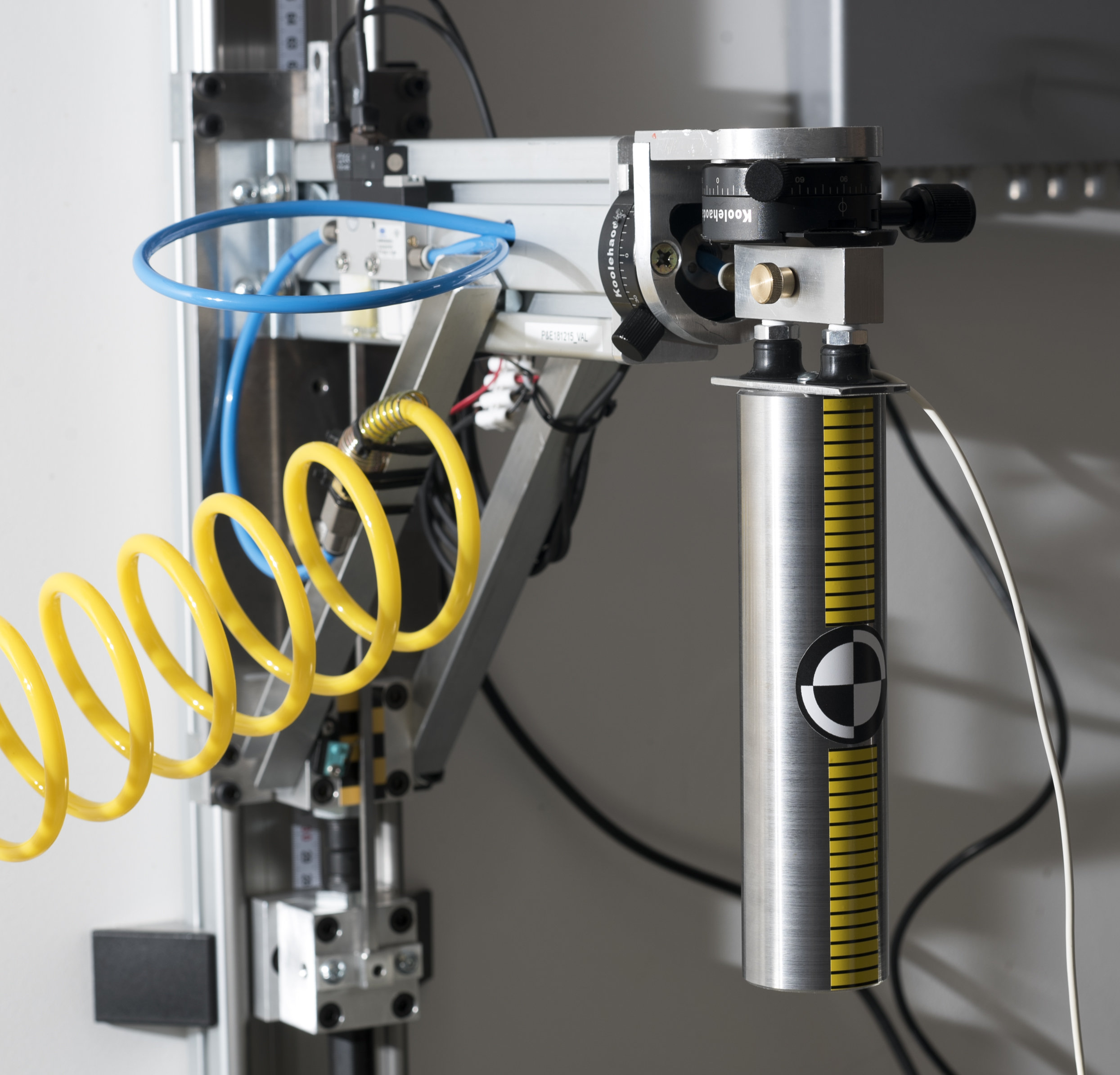
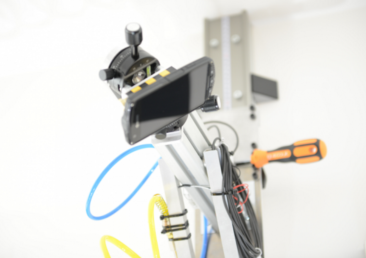
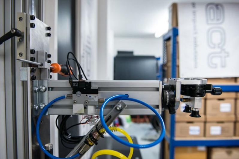
This resulted in the design and manufacture of the SDR 2200, a bespoke, linear system that guides the device to be tested to the impact surface. By making use of an air vacuum and suction cups mounted to a fully adjustable head, the item is guided to the drop surface at a specific orientation and then released prior to impact. This provided a very consistent impact orientation and velocity and meant that we could repeat the load case detailed in MIL-STD-810G and make a direct comparison between various phone models.
Its open and flexible installation allows for various load cases for drop heights upto 2.2m. The vacuum system can carry components upto 3kg which means that items can be impacted by a falling weight which is useful for the compression testing of foams. It is perfect for materials characterisation and an invaluable tool for CAE model correlation.
The SDR 2200 is designed to be used with instrumentation and since commissioning it has been developed to include remote solenoid release, impact velocity (using light gate/fringe with raspberry Pi) and trigger for high speed camera.
Small Flying Wedge (SFLW)
Design and manufacture of a test rig for materials characterisation at high strain rates
In 2013 Simpact acquired a unique and very special piece of test equipment from the University of Leeds, Dept of Mechanical Engineering. The Flying Wedge (FLW) impact test facility was a dynamic tensile testing facility capable of generating strain rates from around 10^2s-1 up to in excess of 10^4s-1. It was used mainly for studying the effect of strain rate on materials and generating the data required for the material cards within the non-linear hydrocodes such as RADIOSS and LS-DYNA3D. (Much of this work is referenced by several journal papers published in the International Journal of Impact Engineering)
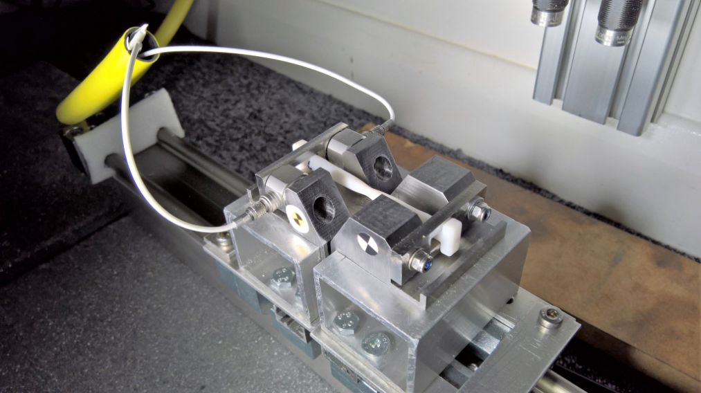
Although it was not possible to recommission the original FLW (due to the H&S of the HP air system), in 2016 we successfully applied the main principle of the flying wedge by designing and integrating a smaller version with our in-house SDR 2200 drop test facility. Here the wedge impactor is mounted vertically to the drop arm of the SDR 2200 and the specimen is forced apart horizontally.
The video on the left is a rendering of the FLW CAD and shows the main principle of operation. In our first project using the rig (characterising the strain rate dependency of 3D printed specimens) we acheived strain rates in excess of 10^3s-1. The SFLW is designed to accommodate donut type load cells for dynamic load measurement and used in conjunction with a high speed camera, a detailed video analysis of the knecking sample w.r.t time can be achieved.
High Speed Pneumatic Launcher – SPL 6000
Design and manufacture of a test rig for high speed impact testing
Appendix B of Railway Group Standard GM/RT2100 describes an impact test procedure for bodyside windows. A ¼kg steel sphere traveling at 50 or 100km/h +/- 3km/h is required to load the toughened or laminated safety glass respectively.
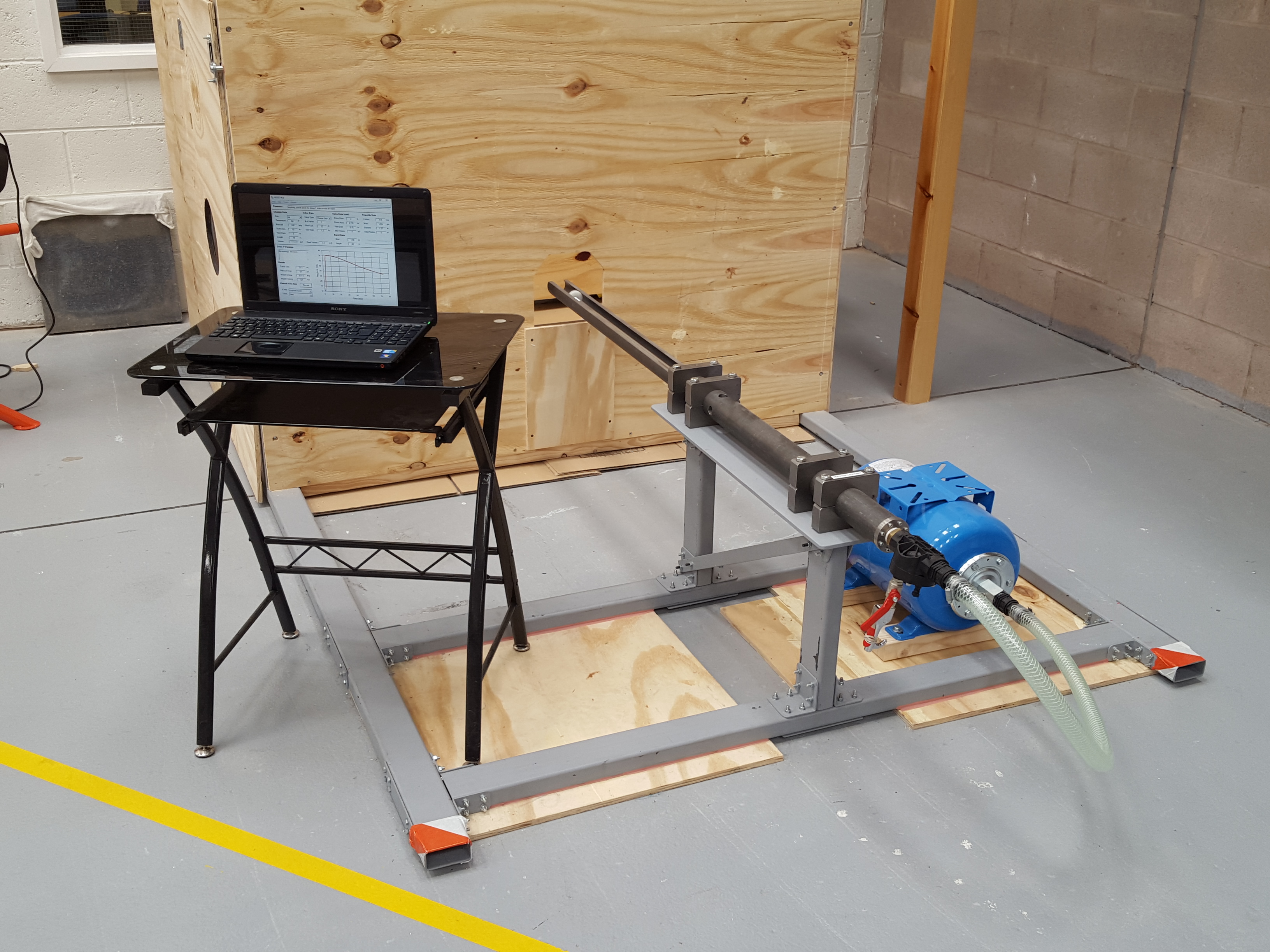
Our rail customer asked if Simpact could design and build a test rig that could be used to test train windows in a controlled manner to the above test procedure. With our background in impact design, knowledge on ballistics, experimental testing and firearms regulations, we were in a perfect position to deliver this request. Starting with deriving a cost effective concept making use of mostly standard parts, we designed a facility that could deliver the required 97J kinetic energy but one that did not infringe on UK firearms regulations that limit projectile energy to 16J maximum.
The developed design of the launch system included a remote trigger and trigger lock and is powered by an 8 bar compressor. After successful testing of the train windows, the test facility remained on-site and has been developed to propel a range of adaptors and sabots allowing for the acceleration of a variety of objects.