Defence
The application of 3D Digital Image Correlation (DIC) to blast load cases
Our defence client came to us asking for us to provide an accurate calculation of dynamic displacements in 3D during a blast load case

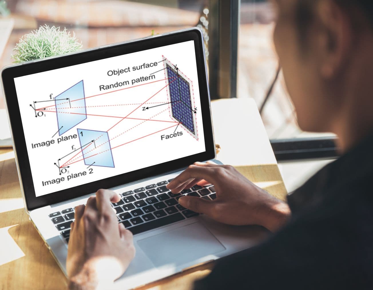
What is 3D DIC and how does it work?
3D Digital Image Correlation (DIC) is an optical Computer Aided Engineering (CAE) method that makes use of stereoscopic technology to track displacements and strains of a target surface over time. The surface is tracked by using a random surface pattern (commonly referred to as “speckling”).
Applying DIC to blast testing of armour
An explosion is a blindingly fast event. The role of the armour is to protect people’s lives, and it does so by shielding them from the blast and absorbing part of its energy. The armour undergoes both elastic and plastic deformation. The full event is over in about 1/10th of the time that it would take you to blink, and by that time the residual shape of the armour bears no resemblance to the peak dynamic deformation that it had undergone just a few milliseconds earlier. In armour design, it is of paramount importance to measure this peak dynamic deformation. If the armour deforms too much, it might for example injure or kill the occupants of a vehicle. Test houses typically rely on shorting pins or honeycombs to gain an understanding of maximum dynamic deflection. These measurement methods have severe limitations, as they provide limited information and can get destroyed in the loadcase.
Advantages of 3D DIC
3D DIC provides a number of unique advantages;
- As a non-contact optical technique, there is no need for any physical instrumentation to be attached to the armour.
- Data is captured for the entire surface, as opposed to physical techniques (i.e. shorting pins) which only measure displacements in a particular area. DIC extracts data from the whole visible surface and measures not only how much it deforms, but also how it deforms.
- A wealth of information. DIC extracts 3D information on displacements, strains, velocities and accelerations.

A CAE Analyst's dream
The ultimate value of DIC and where it stands head and shoulders over traditional techniques is when used in conjunction with Computer Aided Engineering. By allowing the user to generate time-dependent contour plots, DIC bridges the gap between Finite Element Analysis (FEA) and experimental testing and is the ultimate correlation tool for CAE model correlation.

Blast Load Case - Experimental Set-Up and Calibration Process
Results - Data Capture and Correlation
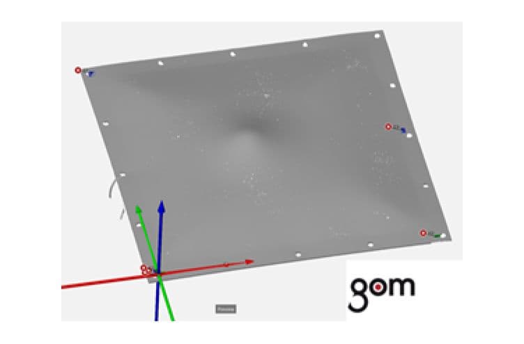
For the experiments a number of 6 mm-thick ARMOX (armoured steel) plates were used. These were speckled by hand after degreasing and application of a white base coat of paint.
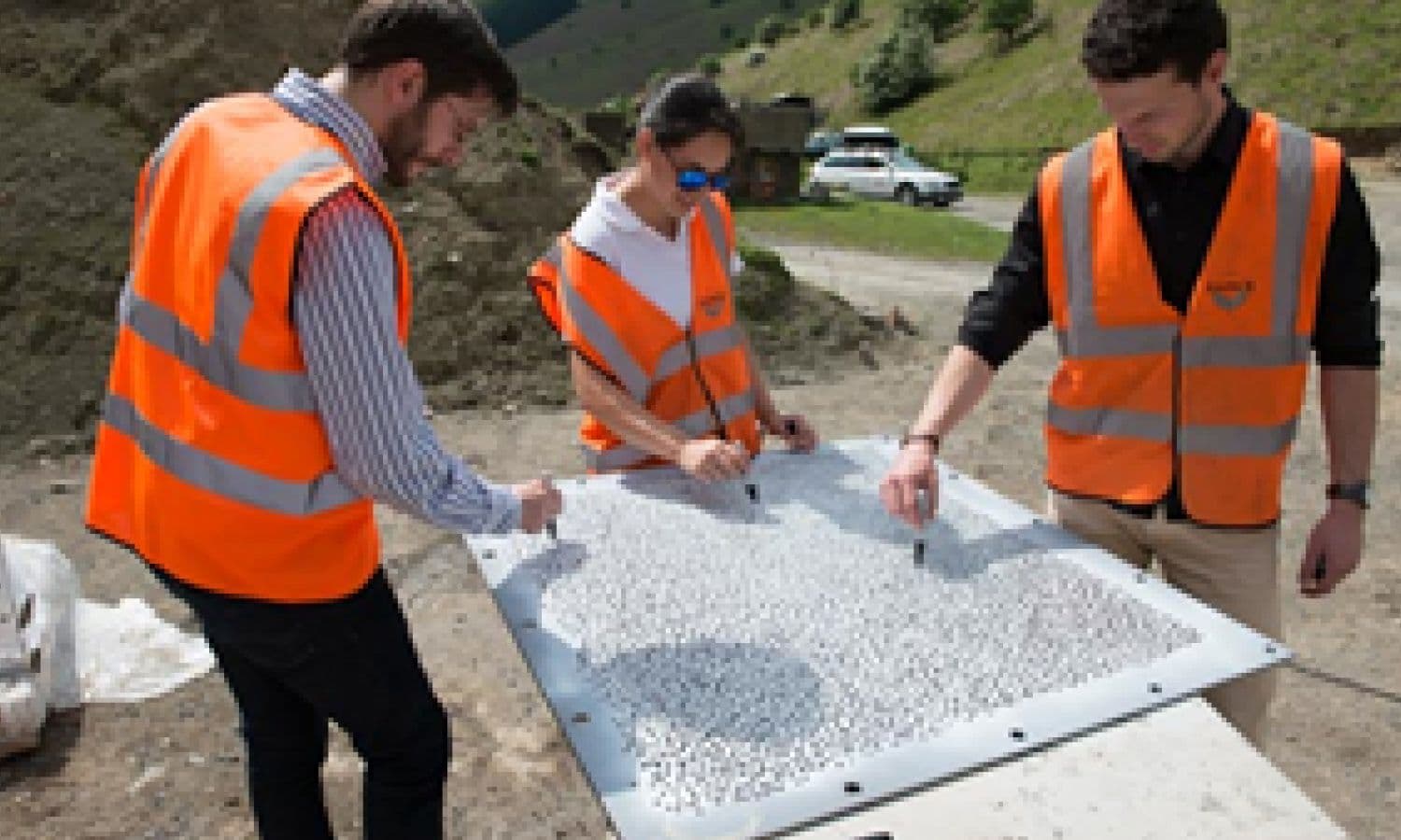
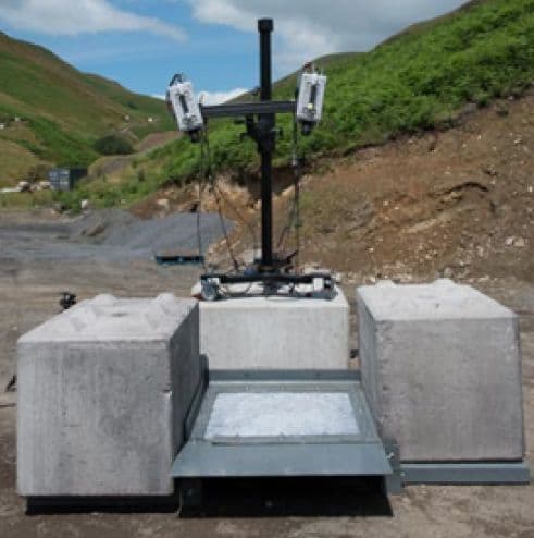
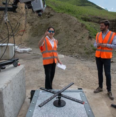
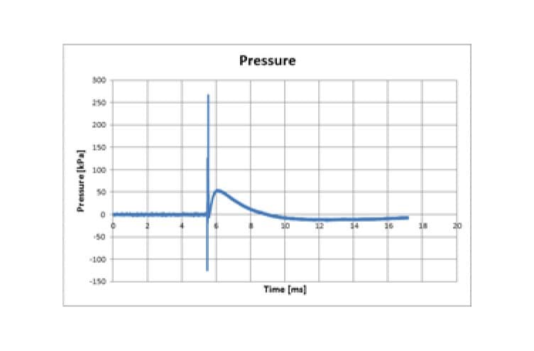
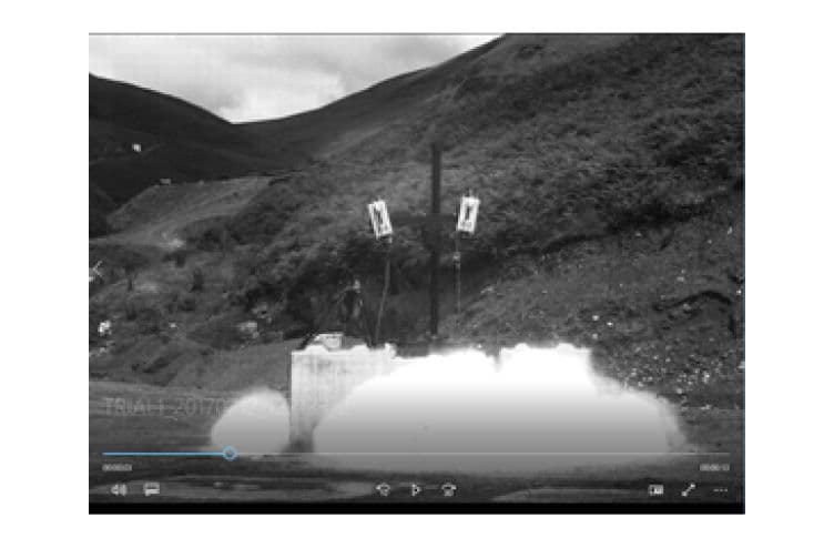
Key to delivering a successful DIC analysis is to achieve a high-quality calibration which derives the exact relative position and orientation of the cameras with respect to each other. The GOM 3D DIC software and calibration hardware was used to capture and process the series of images from the high-speed cameras. A pressure transducer was placed at a set distance to the charge. After calibration was complete, it was time to set off the charges.
Results - Data Capture and Correlation
The data captured included high-speed videos from 3 cameras and pressure data.
The DIC analysis was successful. Peak dynamic deformation was measured with second-digit precision. The DIC technique was validated by measuring the residual deformation in the Data Capture and comparing this to values obtained by 3D laser scanning of the plates. The results proved an excellent correlation to within less than 2% on the static displacements.

This project was carried out in association with Slowmo (Providing high-speed camera expertise and hire) and the Radnor Range (Providing experimental blast testing capability and facilities)


'DIC is a fantastic technique with unprecedented advantages over existing industry-standard methods’
Get in touch
We would love to hear about your project, get in touch and let’s explore how the expert team at Simpact can take it from design target specification through to verification.