Automotive
ALM Innovation in British Hillclimbing
Additive Layer Manufacturing (ALM), also known as 3D printing or additive manufacturing offers design freedom allowing to minimise weight, important when every gram counts.

Speed
How fast can you get to the top of a hill in a single seater racing car? Sounds pretty simple, doesn’t it? But at the top of this game, British Hillclimbing is a fiercely competitive form of motorsport where drivers seek out even the smallest advantages that can make all the difference between winning and losing.
In a collaboration between Midlands SME, Simpact Engineering Ltd and WMG (Warwick University) project partners have demonstrated significant innovation at this level of motorsport by the combined application of their respective skills and expertise has produced a new front wing and support structure which is almost half the weight of the original design - that’s more than 2kg less weight to take up the hill. This is a delta which the driver will really notice

Loadcases
Although impact loading was an important loadcase for analysis, the performance of the wing to normal in-service loading was the focus of the CAE analysis;
- 1. Aerodynamic loading – evenly distributed (-z)
- 2. 3g bump (-z)
- 3. 3g rear (-y)
- 5. Point loading on wing tip (-z +z), (-x +x), (-y, +y)
- 5. Impact loading (full frontal rigid wall and 45deg kerb impact at 90mph)
The outputs of CAE models require targets to quantify performance and the ambitious target was set to deliver the new system at least half the original weight. This required analysis of the original system to determine key performance indicators (KPI’s)
Strong & Lightweight Design Concept
The key to delivering a successful lightweight design was to use a smart combination of materials and the thorough use of upfront simulation to arrive at the best possible balance of weight and performance. For commercial exploitation, no tooling investment was anticipated and a short production time was essential.
Wing Concept Design
For the wing section we opted for a NACA 6412 profile which is reasonably aggressive and provides good downforce and low drag (at low Reynolds numbers). The profile was inverted and scaled to suit the size of the existing wing and describe the aerodynamic surface of the wing.
We chose to 3D print the ribs in ABS and repeating these at regular intervals, this presented the best solution to define the consistent aerodynamic surface of the main wing. This provided complete geometric freedom when designing in CAD and the ribs would be bonded to a pultruded composite box section which forms the main stringer and a strong backbone for the wing.
Secondary winglets are 3D printed entirely in ABS where the internal core used a lightweight honeycomb geometry (defined by the 3D printer) for its core. The secondary winglets provide extra downforce and help divert air over the front wheels and are mounted outboard enough not to restrict air into the side pods.
The flat endplates control the wingtip vortices and are water jetted from a flat section of carbon fibre comprising of 3 layers and cured in an epoxy resin. The water jetting includes the holes for aluminium rivets used to fasten the endplates and provide angle of attach adjustment on the secondary winglets.
A single ply of polyester film shrink wrapped to the structure which is stiff enough to transfer aerodynamic loads but flexible enough to wrap around the profile. The wing is complete.

Noseframe Concept Design
We derived a simple triangular tubular design to connect the wing to the car. This relatively open spaceframe concept provides an efficient loadpath and marries well to the existing spaceframe chassis.
For the strong and stiff connection which is required between the nose structure and front wing and a component that offered the versatility to adjust wing angle of attack - this was the part selected for metal ALM.

Finite Element Analysis & Optimisation
As the concept CAD design for the complete front wing assembly was in place and CAD for the original nose structure available, a finite element model of the complete front wing assembly was built. The mesh needed to be suitable for both linear and non-linear analysis and made use of a combination of finite elements depending on their suitability including beams, shells and 3D elements.
This information and a target setting exercise on the allowable displacements provided the inputs required for a topology optimisation exercise to derive the basic shape of the metal ALM component. The only constraints being the design volume available and the design for the fixation/adjustment. The image below shows the evolution of the design in Optistruct.
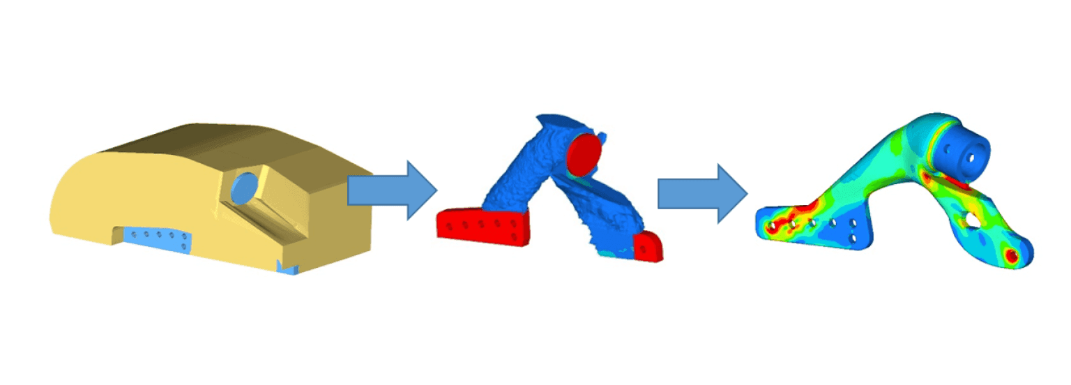
The baseline optimisation drove the v-shaped bracket shown above and the need for a high strength material. Maraging steel was chosen for the sinter material as the EOS data sheet offered very good material properties (2000MPa yield stress) and part accuracy. Although the above derived design was solid in section at this stage of the optimisation, it enabled the detailed analysis, fine-tuning and weight reduction of the complete system and other wing component assemblies.
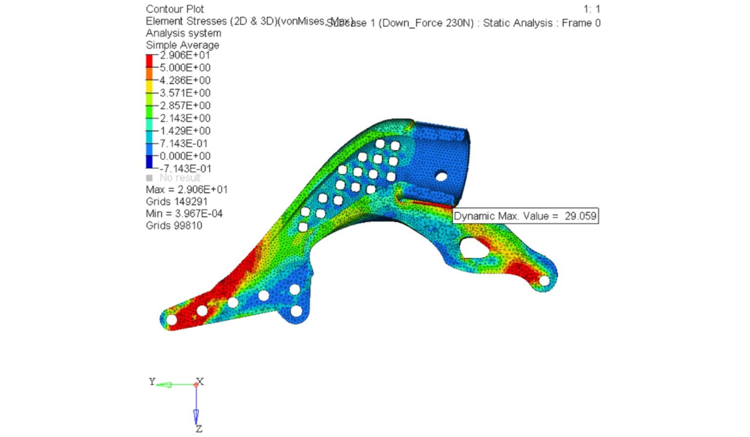
By analysing the component stresses in relation to the material limiting values and considering a factor of safety, we were able to fine tune material thicknesses down to thinnest available and drive as much weight out of the system as possible.
This led to a much lighter version of the metal ALM bracket which weighed just 144gms (was 210gms).
A cross section of the model is shown on the right and the hollow section also allows for un-sintered support material to be removed post manufacture.

CAD Detailing
The CAD was updated to include the recommendations from the FE analysis and detailed for manufacture. The CAD is then converted to an STL file and the part is ready for manufacture on the appropriate ALM machine.
Manufacture & Assembly
The front nose structure was manufactured by Arch Motor Co in Huntingdon who are well known for specialising in the manufacture of automotive spaceframes. The supplied Reynolds tubing was braze welded and then powder coated.
The NACA aerofoil profiles were printed in ABS overnight on the Fortus 3D printer at WMG. These were then adhesively bonded to a composite pultrusion making up the main backbone of the wing.
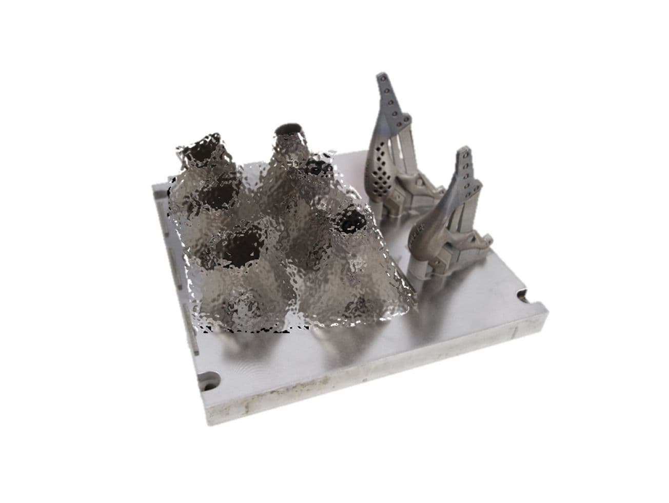
The metal ALM brackets are shown to the right (with customer confidential items blurred) after SLS printing on the EOSINT M280. These are then heat treated to relieve residual stresses and a wire erosion process is used to cut the brackets from the bedplate and remove unwanted build material.

Conclusions & Testing
With the first prototype of the wing now built and the new noseframe in production, it was time to test the assembly at a local test track (Curborough Sprint Course in Lichfield) and the picture below shows the car accelerating out of the Fradley Hairpin.
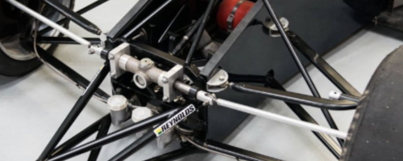
The second set of photos show the car back at our workshop complete with Reynolds lightweight noseframe and metal ALM brackets.
Want to find out more about this project?
Download the case study
Get in touch
We would love to hear about your project, get in touch and let’s explore how the expert team at Simpact can take it from design target specification through to verification.